TO TURN ON THE LED USING LPC2148
SIMULATOR: PROTEUS 8.0
SOFTWARE: KEIL
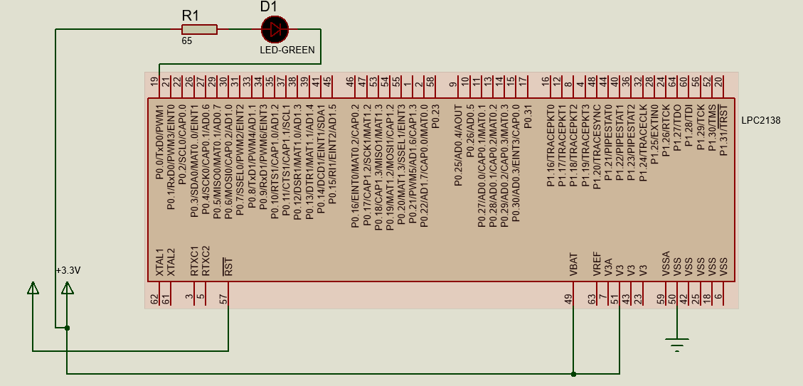
CIRCUIT DIAGRAM:
WORKING:
This project is about turning on the led connected to P0.0 pin of lpc 2148.In this project,LED is connected in current sinking arrangement.
Whenever logic 0 is provided to P0.0 pin of lpc 2148, LED get turned ON.As in this project current sinking arrangement is used hence logic 0 is provided to turn on the led.
PROGRAM:
#include<LPC214x.h> // Header file of LPC2148
int main()
IODIR0=0x00000001;// select p0.1 as an output pin
PINSEL0=0x00000000; // select gpio function of p0.1
while(1) // continuous loop
{
IOCLR0 = 0x00000001;//turn on the led
}
}
PROGRAM DESCRIPTION:
Here,using IODIR register p0.0 pin is set as an output pin.PINSEL0 register is used to select the GPIO(General purpose input/output pin) function of the pin.Using IOCLR register logic 0 is provided to port 0.0 pin.While loop is used for the continuous process.
VIDEO:
Note:


Comments
Post a Comment