Digital Thermometer using 8051 and ADC 0808 Interfacing With 8051
SOFTWARE: KEIL MICRO VISION 4
SIMULATOR:PROTEUS 8.0
CIRCUIT DIAGRAM:
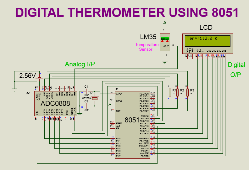
Here,Temperature is taken from LM35 temperature sensor.LM35 converts surrounding temperature into analog voltage(equivalent to temperature).This analog voltage is provided to ADC0808 for digital conversion.
After digital conversion,final temperature get displayed on LCD display.
- RS,RW,EN pins are connected to P2.5 to P2.7 of 8051 respectively.
- Data pins (D0 to D7) are connected to P3.0 to P3.7 of 8051 respectively.
LM35 SENSOR:
- VCC pin is connected to 5 v supply.
- VOUT pin is connected to IN0 channel of ADC 0808.
- On the VOUT pin we get equivalent voltage with respect to the surrounding temperature.
- Temperature change is 10 mv/°c.
- GND pin is connected to GND.
ADC 0808:
- VCC pin is connected to 5 v supply.
- VREF(+) pin is connected to 2.56V supply.
- VREF(-) pin is connected to GND.
- OUT8(LSB) to OUT1(MSB) pins are connected to P1.0(LSB) to P1.7(MSB) respectively.i.e. OUT8 pin is connected to P1.0 and OUT 7 pin is connected to P1.1 and so on.Likewise all the pins are connected.
- START pin is connected to P2.1 of 8051.
- ALE pin is connected to P2.3 of 8051.
- OE pin is connected to P2.4 of 8051.
- EOC pin is connected to P2.0 of 8051.
- ADDC,ADDB,ADDA pins are connected to P0.7 to P0.5 respectively.
- CLOCK pin is connected to P2.2 of 8051.
According to step sequence adc converts the value.
Here,Step size = [vref(+) - vref(-)] / [2^8];
Here supposed vref(+) is connected to VCC pin of ADC 0808 then step size is equal to 19.53mv.
Calculation of vref(+) with step size of 10mv:
- 10*10^-3=[vref(+) - 0v]/256
- vref(+)=(10*10^-3)*(256)
- vref(+)=2.56v
Steps to interface with ADC0808:
1.Provide clock signal of frequency (10 khz upto 640 khz)on clock pin of ADC 0808.I have selected the frequency of 15khz.Make EOC an input pin.Clear START,ALE and OE pin of ADC0808.
2.Select the appropriate channel by sending signal to ADDA, ADDB, ADDC pin of ADC0808. |
| CHANNEL SELECTION TABLE OF ADC 0808 |
4.Send high to low pulse on ALE pin of ADC0808.
5.Wait for EOC(End of conversation)signal to become high to low.
6.Make OE(Output enable) pin high.7.Take the data from the port of 8051 where output pins(OUT1 to OUT8) of ADC 0808 are connected.
Here I have connected output pins of ADC 0808 to Port 1 of 8051.Hence I have taken data from Port 1.
8.Clear OE pin.
9.Repeat the steps from step 2 for continuous conversion.
PROGRAM:
#include<reg51.h>
#include<string.h>
sbit RS = P2^5;
sbit RW = P2^6;
sbit EN = P2^7;
sbit ale=P2^3;
sbit oe=P2^4;
sbit start=P2^1;
sbit eoc=P2^0;
sbit clk=P2^2;
sbit chc=P0^7; //Address pins for selecting input channels.
sbit chb=P0^6;
sbit cha=P0^5;
void delay(int t);
void lcd_init(void);
void lcd_command(char c);
void lcd_data(char d);
void str(char a[]);
void print( long float p);
long float k;
unsigned long int q,r,x,y,z;
void timer0() interrupt 1 // TIMER 0 interrupt ISR
{
clk=~clk;
}
void main() // MAIN PROGRAM
{
lcd_init(); // lcd initialization
str("!!welcome!!");
lcd_command(0x01); // clear display
str("Temp:");
lcd_command(96); //custom character (°c) display
lcd_data(0x10);
lcd_data(0x07);
lcd_data(0x08);
lcd_data(0x08);
lcd_data(0x08);
lcd_data(0x08);
lcd_data(0x07);
lcd_command(0x8b);
lcd_data(4);
eoc=1; // make eoc an input
ale=0;
oe=0;
start=0;
TMOD=0x02; // timer 0 in mode 2
TH0=0xc2; // 15khz
IE=0x82; // set timer 0 interrupt
TR0=1; // start timer 0
while(1)
{
chc=0; // select channel 0
chb=0;
cha=0;
ale=1; // send high to low pulse on start and ale pin
start=1;
delay(1);
ale=0;
start=0;
while(eoc==1); // wait for conversion
while(eoc==0);
oe=1;
k=P1;
lcd_command(0x85);
print(k); // send the digital data to lcd
oe=0;
}
void str(char a[]) // lcd function to display string
{
int j;
for(j=0;a[j]!='\0';j++)
{
lcd_data(a[j]);
}
}
void lcd_init(void) // lcd initialization
{
lcd_command(0x38); //8 bit,2 line,5 x 8 dots
lcd_command(0x01); // clear display
lcd_command(0x0f); // display on,cursor blinking
lcd_command(0x06); // entry mode
lcd_command(0x0c); //cursor off
lcd_command(0x80);//Force cursor to the begining of the first row
}
void lcd_command(char c) // lcd command function
{
P3=c;
RS=0; // select command register
RW=0;
EN=1;
delay(5);
EN=0;
delay(5);
}
void lcd_data(char d) // lcd data function
{
P3=d;
RS=1; // select data register
RW=0;
EN=1;
delay(5);
EN=0;
delay(5);
}
void delay(int t) // delay function
{
int j;
for(j=0;j<t*1275;j++);
}
void print( long float p) // number display function
{
x=p*10;if(x>=1000)
{
q=x/1000;
q=q+48;
y=(x%1000)/100;
y=y+48;
z=((x%1000)%100)/10;
z=z+48;
r=x%10;
r=r+48;
lcd_data(q);
lcd_data(y);
lcd_data(z);
lcd_data(46); // ASCII value of point
lcd_data(r);
}
else
{
q=x/100;
q=q+48;
y=(x%100)/10;
y=y+48;
z=x%10;
z=z+48;
lcd_data(q);
lcd_data(y);
lcd_data(46); // ASCII value of point
lcd_data(z);
r=0;
lcd_data(r);
}
PROGRAM DESCRIPTION:
First I have initialized the lcd.After that I have displayed the custom character of degree celcius by selecting appropriate pixel of lcd.For generating the clock signal on clock pin of adc 0808,I have used timer 0 interrupt.
After that I have followed the steps mentioned above(steps for ADC 0808 interfacing).Output is taken from port 1 of 8051 and send to the lcd display.
Calculation of the value loaded in TH0 register:
2.1 / (921600) = 1.08*10^-6
3.I want to generate 15 khz frequency.
4.So required time= 1/(15*10^3) = 6.66*10^-5
5.Count= required time / controller time
6.Count = (6.66*10^-5) / (1.08*10^-6)
7.Count = 61.72=62
8.Value to be loaded in timer 0 register= 256 - 62= 194= c2(hex)
9.So in TH0=0xc2 data get loaded.
Note:
1.Please refer the below link to know the interfacing of lcd.
http://embeddedprojects222.blogspot.com/2020/07/lcd-interfacing-using-8051-micro.html
2.Please refer the below link to know how to display numbers on an lcd.
http://embeddedprojects222.blogspot.com/2020/07/how-to-display-number-on-lcd.html
3.Please refer the below link to know how to display custom character on the lcd.
https://embeddedprojects222.blogspot.com/2020/09/to-display-custom-characters-on-lcd.html


Comments
Post a Comment