Posts

Showing posts with the label lcd

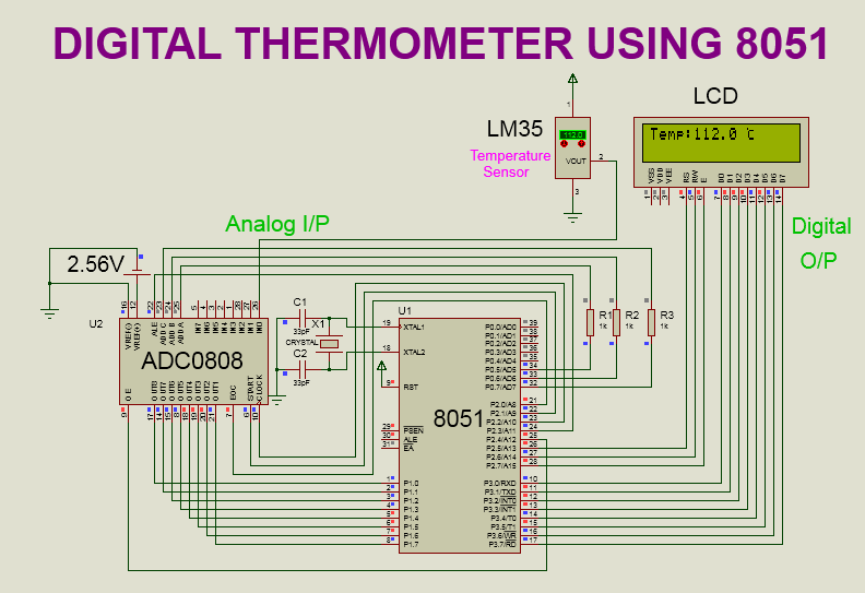
LCD interfacing using AVR(ATMEGA 32)

Image
SIMULATOR: PROTEUS 8.0 SOFTWARE: KEIL 4.0 CIRCUIT DIAGRAM: PIN DESCRIPTION OF LCD: PROGRAM: #include<avr/io.h>   // header file for AVR #include<util/delay.h> // header file for delay function void lcd_init(void); void lcd_command(char c); void lcd_data(char d); void str(char a[]); int main(void)    // main program   { DDRB=0XFF;  //  Select PORT B as an output port DDRD=0XFF; // Select PORT D as an output port lcd_init();      // initialize the lcd while(1)             // continuous loop   { str("WELCOME TO THE");  lcd_command(0xc0);                  // move cursor to the next line str("EMBEDDED SYSTEM"); lcd_command(0x01);           // clear display } } void lcd_init(void)  // lcd initialization function { lcd_command(0x38); //8bit,2 line,5*7 matrix lcd_command(0x0c); //cursor off,display on lcd_command(0x80);//force cursor to the beginning of the first line lcd_command(0x01);// clear display lcd_co

LCD interfacing in 4 bit mode using 8051

Image
  SOFTWARE: KEIL MICRO VISION 4.0 SIMULATOR: PROTEUS 8.0 CIRCUIT DIAGRAM: PIN DESCRIPTION: PROGRAM: #include<reg51.h> sbit RS = P1^0; sbit EN = P1^1; void lcd_init(void); // lcd initialization function void lcd_command(unsigned char c);// lcd command function void lcd_data(unsigned char d);// lcd data function void lcd_string(unsigned char *ch);// string display function void delay(unsigned int t); // delay function int main() { lcd_init(); lcd_string("Welcome to the"); lcd_command(0xc0);// shift cursor to second row lcd_string("Embedded System"); while(1); } void lcd_init() { lcd_command(0x02);// 4 bit mode lcd_command(0x28);//4 bit mode,2 line,5x7 matrix lcd_command(0x0C); // display on,cursor off lcd_command(0x06); // entry mode lcd_command(0x01); // clear display lcd_command(0x80); // first location(begining) } void lcd_command(unsigned char c) { P1=(P1&0x0f)|(c&0xf0);// send higher nibble RS=0; // select command register EN=1; // send high

To display custom characters on the lcd using 8051 micro-controller.

Image
SOFTWARE:   KEIL MICRO VISION 4 SIMULATOR:   PROTEUS 8.0 CIRCUIT DIAGRAM: WORKING: This project is about displaying custom characters on the lcd.Simple meaning of custom character is the character which is not available on the keyboard or which is made by modifying original characters. In the lcd display,to display characters which are already available in the form of ascii value (from 'a' to 'z' or any other characters) we do not need to do anything.By sending the ascii value or sending the character directly to the lcd we can able to display those characters(which are already available) on the lcd. In the lcd display,there is one controller which control all the operations of the lcd.Lcd controller has a memory called  CG-RAM(character generator random access memory)  which is used to create and store the custom character. Size of the CG-RAM is 64 bytes. At a time we can able to display 8 custom characters(for 5*8 matrix) and 4 custom characters(for 5*10 matrix) on th

Digital Thermometer using 8051 and ADC 0808 Interfacing With 8051

Image
SOFTWARE: KEIL MICRO VISION 4 SIMULATOR: PROTEUS 8.0 CIRCUIT DIAGRAM: WORKING: Here,Temperature is taken from LM35 temperature sensor.LM35 converts surrounding temperature into analog voltage(equivalent to temperature).This analog voltage is provided to ADC0808 for digital conversion. After digital conversion,final temperature get displayed on LCD display. LCD(16X2) DISPLAY: RS,RW,EN pins are connected to P2.5 to P2.7 of 8051 respectively. Data pins (D0 to D7) are connected to P3.0 to P3.7 of 8051 respectively. LM35 SENSOR: VCC pin is connected to 5 v supply. VOUT pin is connected to IN0 channel of ADC 0808. On the VOUT pin we get equivalent voltage with respect to the surrounding  temperature. Temperature change is 10 mv/°c. GND pin is connected to GND. ADC 0808: VCC pin is connected to 5 v supply. VREF(+) pin is connected to 2.56V supply. VREF(-) pin is connected to GND. OUT8(LSB) to OUT1(MSB) pins are connected to P1.0(LSB) to P1.7(MSB) respectively.i.e. OUT8 pin is connected to P1.