LCD interfacing in 4 bit mode using 8051
SOFTWARE: KEIL MICRO VISION 4.0
SIMULATOR: PROTEUS 8.0
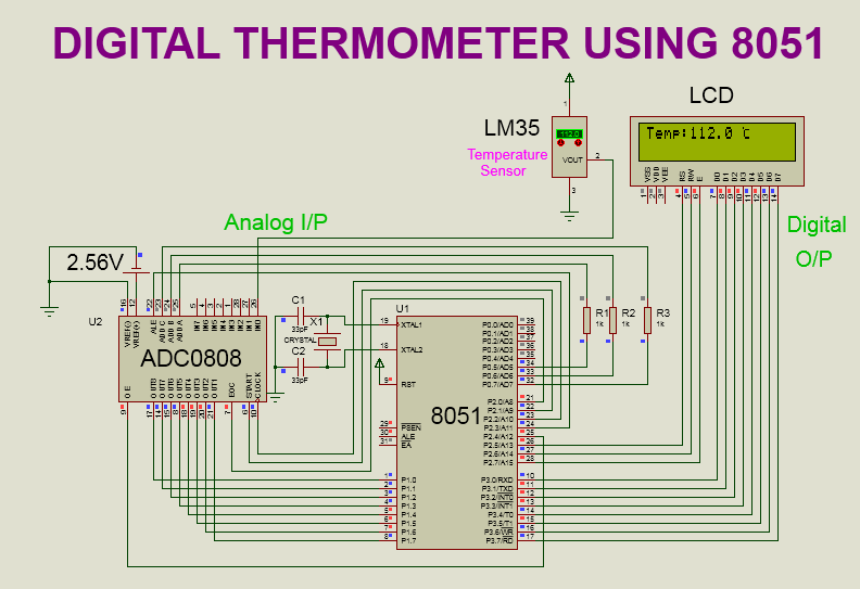
CIRCUIT DIAGRAM:

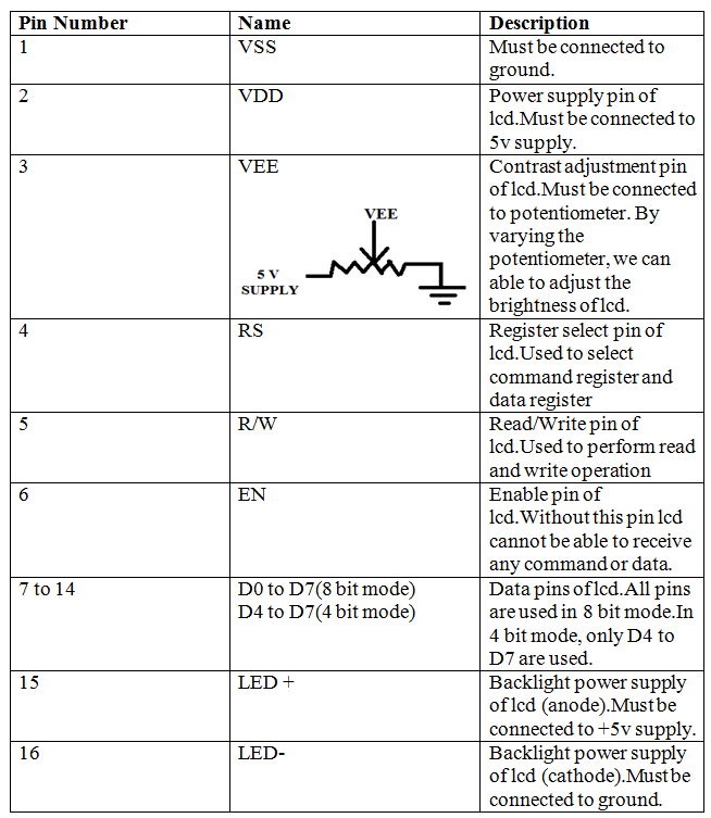
PIN DESCRIPTION:

PROGRAM:
#include<reg51.h>
sbit RS = P1^0;
sbit EN = P1^1;
void lcd_init(void); // lcd initialization function
void lcd_command(unsigned char c);// lcd command function
void lcd_data(unsigned char d);// lcd data function
void lcd_string(unsigned char *ch);// string display function
void delay(unsigned int t); // delay function
int main()
{
lcd_init();
lcd_string("Welcome to the");
lcd_command(0xc0);// shift cursor to second row
lcd_string("Embedded System");
while(1);
}
void lcd_init()
{
lcd_command(0x02);// 4 bit mode
lcd_command(0x28);//4 bit mode,2 line,5x7 matrix
lcd_command(0x0C); // display on,cursor off
lcd_command(0x06); // entry mode
lcd_command(0x01); // clear display
lcd_command(0x80); // first location(begining)
}
void lcd_command(unsigned char c)
{
P1=(P1&0x0f)|(c&0xf0);// send higher nibble
RS=0; // select command register
EN=1; // send high to low pulse on enable pin
delay(2);
EN=0;
P1=(P1&0x0f)|(c<<4);// send lower nibble
EN=1; // send high to low pulse on enable pin
delay(2);
EN=0;
delay(4);
}
void lcd_data(unsigned char d)
{
P1=(P1&0x0f)|(d&0xf0);// send higher nibble
RS=1; // select data register
EN=1; // send high to low pulse on enable pin
delay(2);
EN=0;
P1=(P1&0x0f)|(d<<4); // send lower nibble
EN=1; // send high to low pulse on enable pin
delay(2);
EN=0;
delay(4);
}
void lcd_string(unsigned char *ch)
{
while(*ch!='\0')
{
lcd_data(*ch);
ch++;
}
}
void delay(unsigned int t)
{
unsigned int i;
for(i=0;i<t*1240;i++);
}
PROGRAM DESCRIPTION:
In 4 bit mode, it is necessary to provide the data in nibble format. A higher nibble needs to be sent first. After sending each nibble we need to provide the enable signal. Therefore in this program, a higher nibble(d7 to d4) is sent first. After sending the nibble, it is necessary to provide the enable signal. Hence, the enable signal is provided after sending each nibble.
(c<<4) is used to shift the lower bits(d3 to d0) into higher bits position(d7 to d4).Same get followed in lcd_data function.In this (p1 & 0x0f) is used to mask the lower four bits(d3 to d0) of port1.(c & 0xf0 ) is used to send only higher four bits(d7 to d4).
In the main program,I have initialized the lcd by providing the required lcd commands. After that, I have sent the data (which will get displayed on an lcd) in the string format.
In the lcd command function, RS is provided with logic 0 to select the command register. To pass the command to the lcd controller enable pin is provided with high to low pulse. In the string function, I have provided one by one character of a string to the lcd data function.In the lcd data function, all the operations remain the same as performed in the lcd command function. Only RS is provided with '1' to select the data register.Four-bit mode saves the pins of the controller. We can utilize those pins for other operations.
VIDEO:
In 4 bit mode, it is necessary to provide the data in nibble format. A higher nibble needs to be sent first. After sending each nibble we need to provide the enable signal. Therefore in this program, a higher nibble(d7 to d4) is sent first.
After sending the nibble, it is necessary to provide the enable signal. Hence, the enable signal is provided after sending each nibble.
(c<<4) is used to shift the lower bits(d3 to d0) into higher bits position(d7 to d4).Same get followed in lcd_data function.
In this (p1 & 0x0f) is used to mask the lower four bits(d3 to d0) of port1.(c & 0xf0 ) is used to send only higher four bits(d7 to d4).
In the main program,I have initialized the lcd by providing the required lcd commands. After that, I have sent the data (which will get displayed on an lcd) in the string format.
In the lcd command function, RS is provided with logic 0 to select the command register. To pass the command to the lcd controller enable pin is provided with high to low pulse. In the string function, I have provided one by one character of a string to the lcd data function.
In the lcd data function, all the operations remain the same as performed in the lcd command function. Only RS is provided with '1' to select the data register.
Four-bit mode saves the pins of the controller. We can utilize those pins for other operations.
VIDEO:
NOTE:
1.In proteus simulation, there is no need to connect vss, vdd and vee.But when we are practically implementing the circuit, all the pins should be connected as mentioned in pin description table of lcd. Please note that pin d0 to d3 are not used in 4 bit mode.

Comments
Post a Comment