I have used four digit seven segment common anode display panel.Four digit display panel has 8 segment pins to send the data and 4 control pins to control the operation of the display ( 4 single 7 segment display units).Segment pins are connected to port 1 and control pins(1,2,3,4) are connected to port(2.0,2.1,2.2,2.3) pins respectively.
It is common anode (CA) display so in order to activate segment I have provided logic 0 to respective segment (as mentioned in the below table given in the program description).
The four digit display panel consists of four 7 segment(ca) display units.To activate required display unit(single 7 segment display unit ) of 4 digit display panel we need to send logic 1 to the respective control pin of the display unit (single 7 segment display unit) and to deactivate the display unit(single 7 segment display unit) we need to send logic 0.
void display (unsigned long int n) // display number
{
if(n==1000) // number =1000
{
digit=ch[(n/1000)]; //pass the value to port 1
sw1=1;
delay(1);
sw1=0;
digit=ch[((n%1000)/100)]; //pass the value to port 1
sw2=1;
delay(1);
sw2=0;
digit=ch[((((n%1000)%100)/10))]; //pass the value to port 1
sw3=1;
delay(1);
sw3=0;
digit=ch[n%10]; //pass the value to port 1
sw4=1;
delay(1);
sw4=0;
}
else if((n>=100)&&(n<1000)) //for numbers ranging from 100 to 999
{
P2=0X00;
digit=ch[((n%1000)/100)]; //pass the value to port 1
sw2=1;
delay(1);
sw2=0;
digit=ch[((((n%1000)%100)/10))]; //pass the value to port 1
sw3=1;
delay(1);
sw3=0;
digit=ch[n%10]; //pass the value to port 1
sw4=1;
delay(1);
sw4=0;
}
if((n>=10)&&(n<100)) // for numbers ranging from 10 to 99
{
P2=0X00;
digit=ch[((((n%1000)%100)/10))]; //pass the value to port 1
sw3=1;
delay(1);
sw3=0;
digit=ch[n%10]; //pass the value to port 1
sw4=1;
delay(1);
sw4=0;
}
else if(n<10) // for numbers less than 10
{
P2=0x00;
digit=ch[n%10]; //pass the value to port 1
sw4=1;
delay(1);
sw4=0;
}
}
void delay (unsigned int i) // delay generation
{
while(i>0)
{
TMOD=0X01; //timer0 mode 1
TL0=0Xf2; // delay of 1/16 of sec
TH0=0x1d;
TR0=1; // start the timer0
while(TF0==0); // wait for rollover
TR0=0; // stop the timer0
TF0=0; // clear overflow flag of timer0
i--;
}
}
PROGRAM DESCRIPTION:
First I have send the data which needs to be displayed to port 1 where segment pins of display panel are connected.After that I have activated required displays((single 7 segment display unit)) on the display panel using control pins.
I have used persistence of vision to display data on the 4 digit display(ca) panel.In order to achieve this I have activated the required display(single 7 segment display unit)by providing logic 1 to respective control pin and then after (1/16) seconds of delay I have provided logic 0 to that control pin.
For providing the delay I have used timer 0 of 8051 in mode 1(16 bit mode).I have written the program to display number up to 1000.
Calculation of timer value loaded in TH0 and TL0 register:
In micro-controller 8051 frequency is internally divided by 12.
I have taken the micro-controller with 11.0592 MHZ frequency.So the calculation is
(11.0592 MHZ ) / 12 = 921600 HZ
1 / (921600) = 1.08*10^-6
I want to generate delay of 1/16 seconds.
Count= required time / controller time
Count = (1/16) / (1.08*10^-6)
Count = 57870.370=57870
Value to be loaded in timer 0 register= 65536 - 57870 = 7666 = 1df2(hex)
So in TH0=0X1d and TL0 = 0Xf2
I have send the data to port 1 according to the below table.
SOFTWARE: KEIL MICRO VISION 4 SIMULATOR: PROTEUS 8.0 CIRCUIT DIAGRAM: WORKING: This project is about displaying custom characters on the lcd.Simple meaning of custom character is the character which is not available on the keyboard or which is made by modifying original characters. In the lcd display,to display characters which are already available in the form of ascii value (from 'a' to 'z' or any other characters) we do not need to do anything.By sending the ascii value or sending the character directly to the lcd we can able to display those characters(which are already available) on the lcd. In the lcd display,there is one controller which control all the operations of the lcd.Lcd controller has a memory called CG-RAM(character generator random access memory) which is used to create and store the custom character. Size of the CG-RAM is 64 bytes. At a time we can able to display 8 custom characters(for 5*8 matrix) and 4 custom characters(for 5*10 matri...
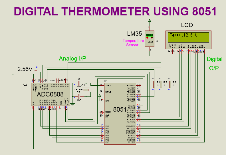
SOFTWARE: KEIL MICRO VISION 4 SIMULATOR: PROTEUS 8.0 CIRCUIT DIAGRAM: WORKING: Here,Temperature is taken from LM35 temperature sensor.LM35 converts surrounding temperature into analog voltage(equivalent to temperature).This analog voltage is provided to ADC0808 for digital conversion. After digital conversion,final temperature get displayed on LCD display. LCD(16X2) DISPLAY: RS,RW,EN pins are connected to P2.5 to P2.7 of 8051 respectively. Data pins (D0 to D7) are connected to P3.0 to P3.7 of 8051 respectively. LM35 SENSOR: VCC pin is connected to 5 v supply. VOUT pin is connected to IN0 channel of ADC 0808. On the VOUT pin we get equivalent voltage with respect to the surrounding temperature. Temperature change is 10 mv/°c. GND pin is connected to GND. ADC 0808: VCC pin is connected to 5 v supply. VREF(+) pin is connected to 2.56V supply. VREF(-) pin is connected to GND. OUT8(LSB) to OUT1(MSB) pins are connected to P1.0(LSB) to P1.7(MSB) respectively.i.e. OUT8 pin is connect...
TIMER INTERFACING WITH 8051: Steps to interface the timer in mode 1: 1.Configure the TMOD register. 2.Load the count value in timer register(TH/TL). 3.Start the timer by setting TR bit of respective timer in TCON register. 4.Wait for the overflow flag to set. 5.Stop the timer. 6.Clear the overflow flag. 7.Repeat the process from step 2. Steps to interface the timer in mode 2: Mode 2 is 8 bit auto reload mode.Hence in this mode there is no need to load the value again in timer register(TH). 1.Configure the TMOD register. 2.Load the count value in timer register(TH). 3.Start the timer by setting TR bit of respective timer in TCON register 4.Wait for the overflow flag to set 5.Stop the timer 6.Clear the overflow flag 7.Repeat the process from step 3. How to calculate the value to be loaded in timer register(TH/TL)? 1. We need to calculate the count value. Count=Required time/Processor time Processor time: In micro-controller 8051,crystal frequency is internally divided by 12.Crystal oscil...


Comments
Post a Comment