Posts

LCD interfacing in 4 bit mode using 8051

Image
  SOFTWARE: KEIL MICRO VISION 4.0 SIMULATOR: PROTEUS 8.0 CIRCUIT DIAGRAM: PIN DESCRIPTION: PROGRAM: #include<reg51.h> sbit RS = P1^0; sbit EN = P1^1; void lcd_init(void); // lcd initialization function void lcd_command(unsigned char c);// lcd command function void lcd_data(unsigned char d);// lcd data function void lcd_string(unsigned char *ch);// string display function void delay(unsigned int t); // delay function int main() { lcd_init(); lcd_string("Welcome to the"); lcd_command(0xc0);// shift cursor to second row lcd_string("Embedded System"); while(1); } void lcd_init() { lcd_command(0x02);// 4 bit mode lcd_command(0x28);//4 bit mode,2 line,5x7 matrix lcd_command(0x0C); // display on,cursor off lcd_command(0x06); // entry mode lcd_command(0x01); // clear display lcd_command(0x80); // first location(begining) } void lcd_command(unsigned char c) { P1=(P1&0x0f)|(c&0xf0);// send higher nibble RS=0; // select command register EN=1; // send high

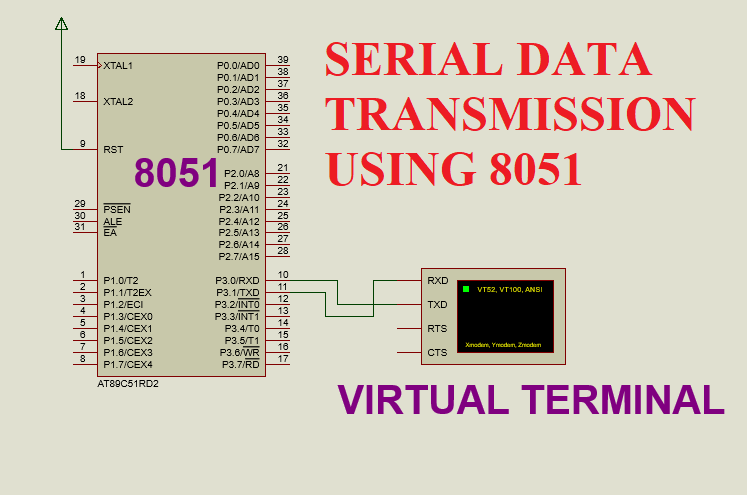
Serial data transmission using 8051

Image
SOFTWARE:   KEIL MICRO VISION 4.0 SIMULATOR:   PROTEUS 8.0 CIRCUIT DIAGRAM: WORKING: Here in this project, I have transmitted the data to the virtual terminal. When all the data gets transmitted, the TI flag in the SCON register becomes equal to 1 which indicates the complete transmission of data(8 bit). Data which needs to be transmitted is first placed into the SBUF register and after that the further procedure is performed as mentioned below.I have used a 9600 baud rate. All the serial communication is done using TXD and RXD pin of 8051. PROGRAM: #include<reg51.h> int main() { unsigned char *d="WELCOME TO THE EMBEDDED SYSTEM"; // data which gets transmitted to the virtual terminal TMOD=0x20; // timer 1 in mode 2 SCON=0x50; // mode 1,8 bit data,1 stop bit,1 start bit TH1=0xfd; // 9600 baud rate TR1=1; // start timer 1 TI=0;   // clear transmit flag while(*d!='\0') { SBUF=*d; // send data to serial buffer d++; while(TI==0); // wait untill transmission is comple

Serial data reception using 8051

Image
SOFTWARE: KEIL MICRO VISION 4.0 SIMULATOR: PROTEUS 8.0 CIRCUIT DIAGRAM: WORKING: Here in this project, I have received the data from the virtual terminal and displayed the received data on an lcd.When all the data get received, the RI flag in the SCON register becomes equal to 1 which indicates the complete reception of data(8 bit). Received data gets stored into the SBUF register. I have taken the received data from the SBUF register and send this data on an lcd. I have used a 9600 baud rate.All the serial communication is done using TXD and RXD pin of 8051. PROGRAM: #include<reg51.h> sbit RS = P2^0;  sbit EN = P2^2; void lcd_init(void); // lcd initialization function void lcd_command(unsigned char c);// lcd command function void lcd_data(unsigned char d);// lcd data function void delay(unsigned int t); // delay function int main() { unsigned char r; lcd_init(); // lcd initialization TMOD=0x20; // timer 1 in mode 2 SCON=0x50; // mode 1,8 bit data,1 stop bit,1 start bit TH1=0xf

Blinking LEDs using AVR (ATMEGA 32)

Image
SIMULATOR:   PROTEUS 8.0 SOFTWARE: WIN AVR CIRCUIT DIAGRAM: CIRCUIT DESCRIPTION: Here, LEDs are connected to the port b register of AVR. I have used the current-sinking arrangement. Therefore, I have provided logic 0 to turn on the LED and logic 1 to turn off the LED. PROGRAM: #include<avr/io.h>     void delay(unsigned int t); // delay function int main(void)     // main program { DDRB=0XFF;   //   Select PORT B as an output port while(1)              // continuous loop { PORTB=0X00;   // turned on the LEDs delay(10); // delay  PORTB=0XFF; // turned off the LEDs } } void delay(unsigned int t) // delay function { unsigned int i; for(i=0;i<1275*t;i++); } PROGRAM DESCRIPTION: DDRx: Here, DDR stands for data direction register and x represents the port number. Here, I have used port b. So, in place of x,I have written B. It is used to decide whether the port is acting as an input port or an output port. DDRx=0X00; // port x is acting as

How to generate one second and one minute delay using timer in 8051?

Image
In 8051 using 11.0592MHZ crystal, we can able to generate a maximum delay of 65536x1.08us=0.07 sec only. By using 8051, we cannot able to obtain the delay which is greater than 0.07 sec. So, to obtain the delay greater than 0.07 sec we need to call millisecond or microsecond delay for a certain amount of time. Supposed I want to generate a delay of one second.To obtain this delay, it is necessary to convert one second into a millisecond or microsecond. We know that, 1 second = 1000 msec We can rewrite the 1000 milliseconds as follows: 50msec*20 = 1000msec Now, according to the calculation mentioned above first, we need to generate a delay of 50 msec and then we need to call this delay 20 times. By doing this we can able to obtain a  delay of 1 sec.By calling one second delay  60 times I have generated one minute delay. ----------------------------------------------------------------------------------- I have written a program to blink the LED for one minute.In between ON/OFF in

To display custom characters on the lcd using 8051 micro-controller.

Image
SOFTWARE:   KEIL MICRO VISION 4 SIMULATOR:   PROTEUS 8.0 CIRCUIT DIAGRAM: WORKING: This project is about displaying custom characters on the lcd.Simple meaning of custom character is the character which is not available on the keyboard or which is made by modifying original characters. In the lcd display,to display characters which are already available in the form of ascii value (from 'a' to 'z' or any other characters) we do not need to do anything.By sending the ascii value or sending the character directly to the lcd we can able to display those characters(which are already available) on the lcd. In the lcd display,there is one controller which control all the operations of the lcd.Lcd controller has a memory called  CG-RAM(character generator random access memory)  which is used to create and store the custom character. Size of the CG-RAM is 64 bytes. At a time we can able to display 8 custom characters(for 5*8 matrix) and 4 custom characters(for 5*10 matrix) on th