Posts

Showing posts from August, 2020

Digital Thermometer using 8051 and ADC 0808 Interfacing With 8051

Image
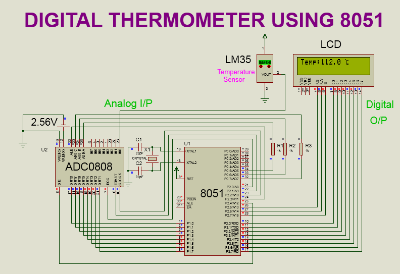
SOFTWARE: KEIL MICRO VISION 4 SIMULATOR: PROTEUS 8.0 CIRCUIT DIAGRAM: WORKING: Here,Temperature is taken from LM35 temperature sensor.LM35 converts surrounding temperature into analog voltage(equivalent to temperature).This analog voltage is provided to ADC0808 for digital conversion. After digital conversion,final temperature get displayed on LCD display. LCD(16X2) DISPLAY: RS,RW,EN pins are connected to P2.5 to P2.7 of 8051 respectively. Data pins (D0 to D7) are connected to P3.0 to P3.7 of 8051 respectively. LM35 SENSOR: VCC pin is connected to 5 v supply. VOUT pin is connected to IN0 channel of ADC 0808. On the VOUT pin we get equivalent voltage with respect to the surrounding  temperature. Temperature change is 10 mv/°c. GND pin is connected to GND. ADC 0808: VCC pin is connected to 5 v supply. VREF(+) pin is connected to 2.56V supply. VREF(-) pin is connected to GND. OUT8(LSB) to OUT1(MSB) pins are connected to P1.0(LSB) to P1.7(MSB) respectively.i.e. OUT8 pin is connected to P1.

Triangular Wave Generation Using 8051

Image
SOFTWARE:   KEIL MICRO VISION 4 SIMULATOR:   KEIL MICRO VISION 4 PROGRAM: #include<reg51.h> void delay(int q); // delay function void main() { while(1) { int i=0; for(i=0;i<=255;i++) // increamenting slope { P1=i;                  // value sending to port 1 delay(5); // delay } for(i=255;i>=0;i--) // decrementing slope { P1=i;             // value sending to port 1 delay(5); // delay }  } } void delay(int q) // delay function { int r; while(q>0) { for(r=0;r<q*1275;r++); q--; } } PROGRAM DESCRIPTION: In this project,I have generated the triangular wave on Port 1 of 8051.  For creating incrementing slope of triangular wave,I have send the values from 0 to 255 to Port 1.I have send one value at a time.After sending each value,I have provided some delay to Port 1.Thus I have created incrementing slope of triangular wave. For creating decrementing slope of triangular wave,I have used the same method.Only the difference is the values from 255 to 0

Timer Interfacing With 8051 and Square Wave Generation With 8051

Image
TIMER INTERFACING WITH 8051: Steps to interface the timer in mode 1: 1.Configure the TMOD register. 2.Load the count value in timer register(TH/TL). 3.Start the timer by setting TR bit of respective timer in TCON register. 4.Wait for the overflow flag to set. 5.Stop the timer. 6.Clear the overflow flag. 7.Repeat the process from step 2. Steps to interface the timer in mode 2: Mode 2 is 8 bit auto reload mode.Hence in this mode there is no need to load the value again in timer register(TH). 1.Configure the TMOD register. 2.Load the count value in timer register(TH). 3.Start the timer by setting TR bit of respective timer in TCON register 4.Wait for the overflow flag to set 5.Stop the timer 6.Clear the overflow flag 7.Repeat the process from step 3. How to calculate the value to be loaded in timer register(TH/TL)? 1. We need to calculate the count value. Count=Required time/Processor time Processor time: In micro-controller 8051,crystal frequency is internally divided by 12.Crystal oscil

Sine Wave Generation Using 8051

Image
SOFTWARE:   KEIL MICRO VISION 4 SIMULATOR:   KEIL MICRO VISION 4 PROGRAM: #include<reg51.h> void delay(void); int a[]={128,164,196,221,240,251,255,255,251,240,221,196,164,128,100,87,62,53,45,45,53,62,87,100}; /* 255=sin 90 251=sin80 240=sin 70 221=sin 60 196=sin 50 164=sin 40 128=sin 30 100= sin 23 87=sin 20 62=sin 14 53=sin 12 45=sin10 */ void main() {  int j; while(1) { for(j=0;j<24;j++) { P1=a[j];         // send sine values to port 1 delay(); }  } } void delay(void) { int r; for(r=0;r<1275;r++); } PROGRAM DESCRIPTION: I have generated sine wave on Port 1 of 8051.I have send the value to Port 1 as per the below calculation.After sending the each value,I have provided some delay. Calculation of sine wave values: Here in 8051,we know that all the ports are 8 bit ports.Hence any port can take the values ranging from 0 to 255 only. Therefore,255 is the maximum value and 0 is the minimum value  any port can take. Maximum value is equivalent to logic 1 and Minimum

TIMER Registers of 8051

Image
This article is about timer registers of 8051. To interface timer with 8051 we need to know the configuration of timer registers. There are two timers in 8051: 1.Timer 0  2.Timer 1. There are two timer registers we need to configured in order to control the operation of the timer and to decide operating mode of the timer. 1.TMOD register(8 bit) 2.TCON register (8 bit) There are two timer registers we need to load the value of the count. 1.Timer 0 register (16 bit):TH0 and TL0 2.Timer 1 register (16 bit):TH1 and TL1 Timer  Register: In order to provide the required delay to the timer,we need to load the count equivalent to delay in timer.For this purpose timer register is used.For timer 0,timer 0 register is used to load the count.For timer 1,timer 1 register is used to load the count. Timer 0 register and Timer 1 register are 16 bit timer registers.As 8051 is a 8 bit controller,hence timer register is used as a separate low byte and high byte register. Timer 0 register is get separated