Posts

Mantra counting machine using 8051 micro- controller.

Image
SOFTWARE: KEIL MICRO VISION 4 SIMULATOR:   PROTEUS 8.0 CIRCUIT DIAGRAM: WORKING: This project is about Mantra counting machine using 8051.In this project,user will be able to count upto  5000 mantras. Lcd display is used to display the count.Data pins of the display are connected to port 1 and control pins (RS,R/W,E) are connected to p3.7,p3.6,p3.5 respectively. T hree buttons(start,stop,reset) are used which are connected to p2.0,p2.6,p3.4 respectively. Working of the buttons are as follows: START: Whenever user presses this button after chanting a mantra counter get incremented by one.Thus mantras get counted. This button needs to be pressed after chanting a mantra otherwise counter will not get incremented and lcd will display the present value of the count. STOP: When this button is pressed,counter stops counting and LCD will displayed the total count of mantras. If the user pressed the 'START' button after pressing this button counter will start counting from the last val

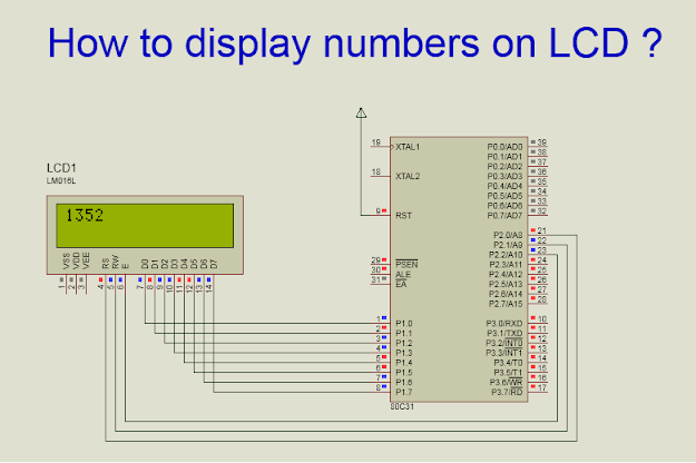
how to display numbers on lcd?

Image
In this article I have written about how number get displayed on lcd. Lcd only displays character ranging from '0' to '9' ( in terms of numbers). So the question is how to display numbers which are greater than 9 ? If we want to display any number which is  greater  than 9 on an lcd then decompose(break) the number and add 48 to each separated digit of that number and send the resulting value one by one to the lcd. Here I have taken four digit number as an example. Suppose I want to display 1352 on lcd. First basic step is initialization  of lcd. Please refer my article about lcd display interfacing with 8051  to know lcd display interfacing. ( http://embeddedprojects222.blogspot.com/2020/07/lcd-interfacing-using-8051-micro.html ). Then the next step is decompose(break) the number. Procedure to decompose(break) 4 digit number: 1.First divide the number by 1000.So we get first number.  Ex.1352/1000=1; 2.Divide the number by 1000 and take the remainder of the             

Traffic light system using 8051 Micro-Controller

Image
SOFTWARE : KEIL MICRO VISION 4 SIMULATOR : PROTEUS 8.0 CIRCUIT DIAGRAM: TRAFFIC LIGHT SYSTEM USING 8051 MICRO-CONTROLLER CIRCUIT WORKING: In this circuit ,I have used three traffic light. signal 1 (P2.0 to P2.2) and signal 2 (P2.3 to P2.5) are connected to port 2 and signal 3 (P3.0 to P3.2) is connected to port 3.Traffic light gets turned on as per the sequence provided in the program. PROGRAM : #include <reg51.h> //signal 1 sbit tl1r = P2^0; // red sbit tl1o = P2^1; // orange sbit tl1g = P2^2; // green //signal 2 sbit tl2r = P2^3; // red sbit tl2o = P2^4; // orange sbit tl2g = P2^5; // green //signal 3 sbit tl3r = P3^0; // red sbit tl3o = P3^1; // orange sbit tl3g = P3^2; // green void delay(int t); void trafficlight(void); void main() // main program { P2=0x00; // turned off the lights P3=0x00; // turned off the lights while(1) { trafficlight(); } } void

Four digit seven segment display interfacing using 8051 Micro-Controller

Image
SOFTWARE: KEIL MICRO VISION 4.0 SIMULATOR: PROTEUS 8.0 CIRCUIT DIAGRAM: CIRCUIT WORKING: I have used four digit seven segment common anode display panel.Four digit display panel has 8 segment pins to send the data and 4 control pins to control the operation of the display ( 4 single 7 segment display units).Segment pins are connected to port 1 and control pins(1,2,3,4) are connected to port(2.0,2.1,2.2,2.3) pins respectively. It is common anode (CA) display so in order to activate segment I have provided logic 0 to respective segment (as mentioned in the below table given in the program description). The four digit display panel consists of four 7 segment(ca) display units.To activate required display unit(single 7 segment display unit ) of 4 digit display panel we need to send logic 1 to the respective control pin of the display unit (single 7 segment display unit) and to deactivate the display unit(single 7 segment display unit) we need to send logic 0. PROGRAM: #include <reg51.